If you’re trying to get started using the Vivado Design Suite, then this guide will help you. Perhaps you’re simply looking for an easy way of getting started using Xilinx’s programmable logic devices, or even programmable logic devices in general. In that case this guide can still help you, but you must accept Xilinx programmable logic devices and the Vivado Design Suite as your starting platform. This guide does intend to get you developing on actual programmable logic hardware, meaning a real physical device. Not only is this a practical way to learn, but it gives you the foundation necessary to start working on your own applications.
You can use any development board built around a programmable logic device that’s compatible with Vivado. Currently all newer Xilinx devices are made to work with Vivado, which includes their 7 Series and UltraScale devices. Digilent’s Basys 3 board was selected for the examples in this guide for the sake of those new to programmable logic.

Digilent’s Basys 3 is a trainer board for introductory FPGA users, and is built around one of Xilinx’s Artix-7 devices. Xilinx does offer a free version of their Vivado Design Suite called WebPACK, and they will also provide you a free non-expiring license for it if you register on their website and provide them some basic information.
Before You Begin
- You’ll of course need to download and install the Xilinx Vivado Design Suite. The free WebPACK version is sufficient to complete this guide (release 2015.4 of WebPACK was used to create it) as long as your target programmable logic device is supported by it. If you need help with installation and setting up your free license Digilent provides a useful guide.
- You’ll also need a suitable development board. If you don’t already have one you can Purchase a Digilent Basys 3 board. Qualified customers can call Digi-Key for reduced academic pricing.
- The Basys 3 doesn’t come with a USB cable, so if you don’t have a spare of the correct type you can purchase one with your Basys 3, or if you would prefer something with more versatility and pizzazz, purchase this one with your Basys 3.
- If you are using a development board that requires an external JTAG programmer or power supply you will of course need these as well. The Basys 3 has these things integrated on board, but if you are using different hardware check your available documentation for instructions.
- You’ll need to connect your JTAG programmer and/or development board to your computer, power it on, and install any necessary drivers.
A Simple Start – Basic Logic and I/O
Here you will start extremely simple, configuring three pins as inputs and three pins as outputs with some simple logic in between. For the Basys 3 example given the first three switches (SW0-SW2) of the board will be connected to the inputs and the first three LEDs (LD0-LD2) to the outputs.
Creating a New Project
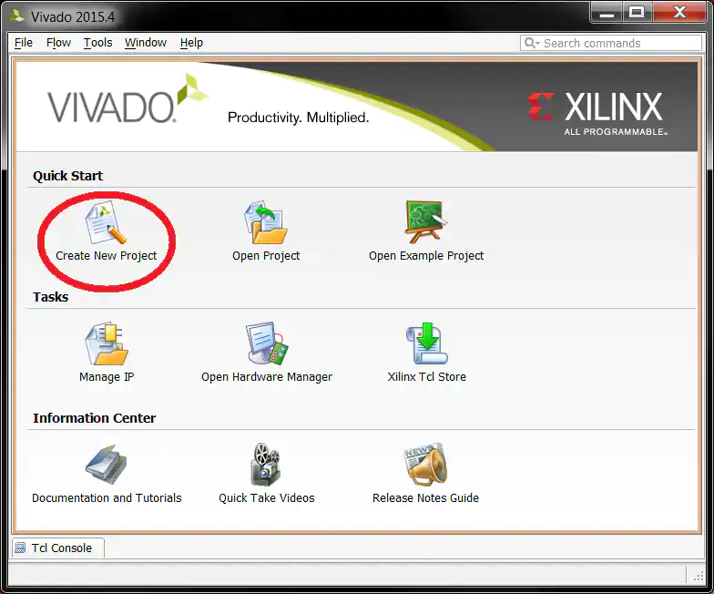
After launching Vivado, from the startup page click the “Create New Project” icon. Alternatively, you can select File → New Project.
The New Project wizard will launch, click the “Next >” button to proceed.

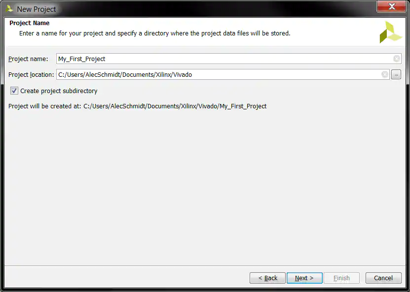
Enter a project name and select a project location. Make certain there are NO SPACES in either! It’s not a bad idea to only use letters, numbers, and underscores as well. If necessary simply create a new directory for your Xilinx Vivado projects in your root drive (e.g. C:\Vivado). You will likely always want to select the “Create project sub-directory” check-box as well. This keeps things neatly organized with a directory for each project and helps avoid problems. Click the “Next >” button to proceed.
Select the “RTL Project” radial and select the “Do not specify sources at this time” check-box. If you don’t select the check-box the wizard will take you through some additional steps to optionally add preexisting items such as VHDL or Verilog source files, Vivado IP blocks, and .XDC constraint files for device pin and timing configuration. For this first project you will add the necessary items later. Click the “Next >” button to proceed.

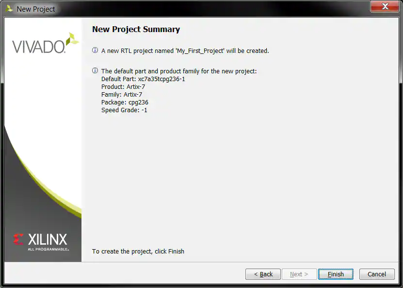
You need to filter down to and select the specific part number for your project. You can physically read the markings on your chip or refer to your board’s documentation to find its part number. In the case of the Basys 3 it’s the Artix-7 chip that’s on the board, and the filters shown will help you get to the correct device that’s highlighted. Once you select the correct device click the “Next >” button to proceed.

Click the “Finish” button and Vivado will proceed to create your project as specified.
Working through the Basic Project Flow
The Vivado project window contains a lot of information, and the information displayed can change depending on what part of the design you currently have open as you work through the steps of your project. Keep this in mind as you work through this guide, because if you don’t see a specific sub-window or sub-window tab it’s possible you aren’t in the correct part of the design.
The “Flow Navigator” on the left side of the screen has all the major project phases organized from top to bottom in their natural chronological order. You begin in the “Project Manager” portion of the flow and the header at the top of the screen next to the Flow Navigator reflects this. This header and the corresponding highlighted section in the Flow Navigator will tell you which phase of the design you have open.

Project Manager
Project Settings
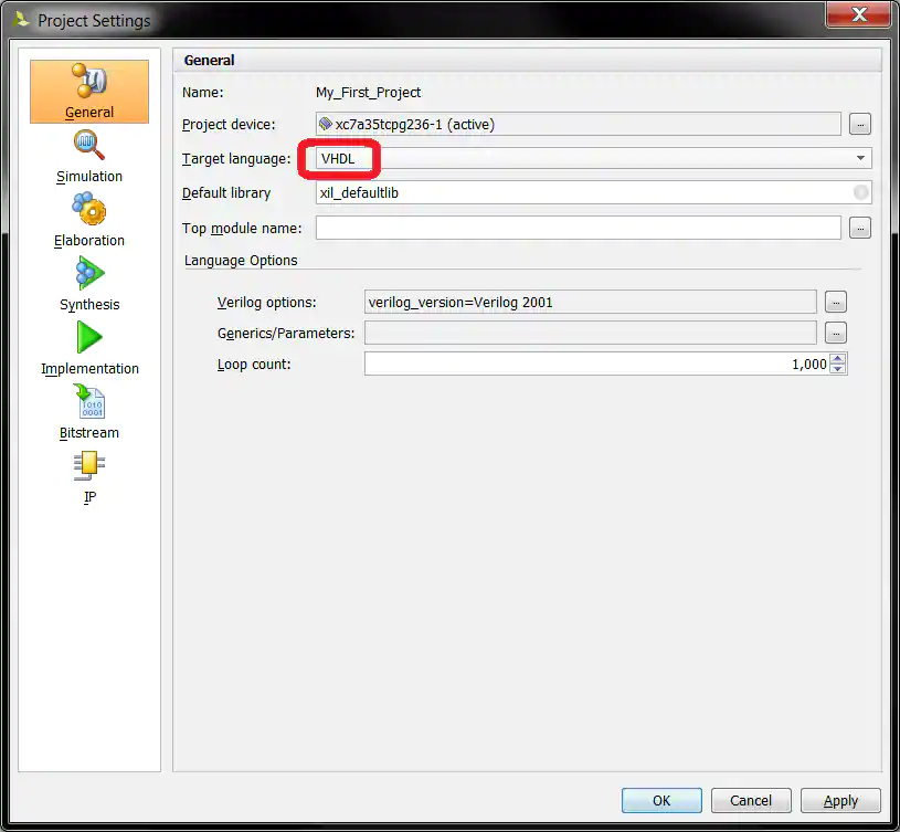
Begin by clicking on “Project Settings” under the Project Manager phase of the Flow Navigator.

There are a lot of settings available here for all phases of the project flow, but for now just select “VHDL” from the drop-down for the “Target language” in the “General” project settings and click the “OK” button.
Add Sources
Now click on “Add Sources” under the Project Manager phase of the Flow Navigator.

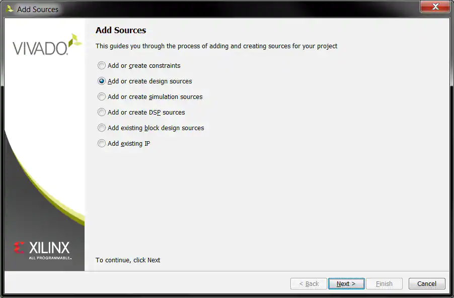
Select the “Add or create design sources” radial and then click the “Next >” button.
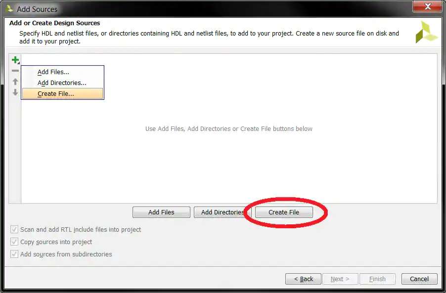
Click the “Create File” button or click the green “+” symbol in the upper left corner and select the “Create File…” option.
Make sure the options shown are selected in the “Create Source File” popup, and for the sake of following along enter “Basic_Logic” for the “File name”. Click the “OK” button when finished.
You can normally enter anything you like for the “File name” as long as it’s valid, but always make certain there are NO SPACES!

Click the “Finish” button and Vivado will then bring up the “Define Module” window.

Define Module
You can use the “Define Module” window to automatically write some of the VHDL code for you. Additional “I/O Port Definitions” can be added by either clicking the green “+” symbol in the upper left or by simply clicking on the next empty line. The “Entity name” and “Architecture name” will be the corresponding VHDL identifiers used in the code, as will whatever is typed in for each “Port Name”. Any valid VHDL identifier can be used for any of these, but for the sake of following along enter the information as shown. Make sure the proper “Direction” is set for each. Click the “OK” button when finished.
Note that if you would rather write your own code from scratch you can simply click the “Cancel” button and Vivado will create a completely blank VHDL source file inside your project. If you click the “OK” button without defining any “I/O Port Definitions” Vivado will still write the basic VHDL code structure but the port definition will be empty and commented out for you to uncomment and fill later.
Also note that the port names here match the silkscreen reference designators of the switches and LEDs on the Basys 3 board that will be utilized for the example. This is for the convenience of those following along with the Basys 3, but should not be inferred as a requirement by beginners; each name is simply an arbitrary identifier.

The VHDL source file generated will be added to your project in the “Design Sources” folder as shown. Double click it and it will open up in a new tab for you to view/edit. All the code here was generated by the previous “Define Module” window, and for this example you only need to manually enter the three highlighted lines between the “begin” and “end” keywords.
Those three lines are:
LD0 <= SW0;
LD1 <= SW1 and SW2;
LD2 <= SW1 or SW2;

This guide is not intended to be a VHDL tutorial, and the above lines are very simple, but for the sake of complete VHDL beginners who need help understanding what behavior to expect:
- The first line simply assigns the “SW0” input directly to the “LD0” output (a buffer).
- The second line assigns the logical-and of inputs “SW1” and “SW2” to the “LD1” output (an AND gate).
- The third line assigns the logical-or of inputs “SW1” and “SW2” to the “LD2” output (an OR gate).
Once the lines are properly entered, select File → Save File from the Vivado top drop-down menu.
RTL Analysis
Open Elaborated Design
Now click on “Open Elaborated Design” under the RTL Analysis phase of the Flow Navigator. You may also get the information popup shown, if so simply click the “OK” button. Vivado will do a little work and then open the Elaborated Design.

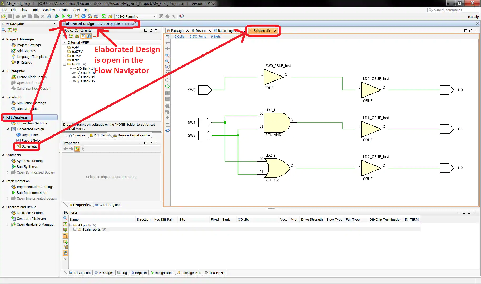
Notice that now the “RTL Analysis” phase is highlighted in the Flow Navigator and the header next to it has changed from “Project Manager” to “Elaborated Design” to indicate you have that stage of the design open and the windows you see pertain to it. If you click back and forth between the “Project Manager” and “RTL Analysis” phases of the Flow Navigator you will see the header and windows change accordingly.
View Schematic
You can click “Schematic” underneath the RTL Analysis phase in the Flow Navigator to open a tab that displays a schematic representation of the previously written VHDL.
Device Pin Assignment
With the Elaborated Design open you can now do your actual programmable logic device pin assignments. Select the “I/O Planning” view from the drop-down in the top bar if it isn’t already, then make sure you are viewing the “I/O Ports” tab at the bottom and click to expand and view all the available ports.
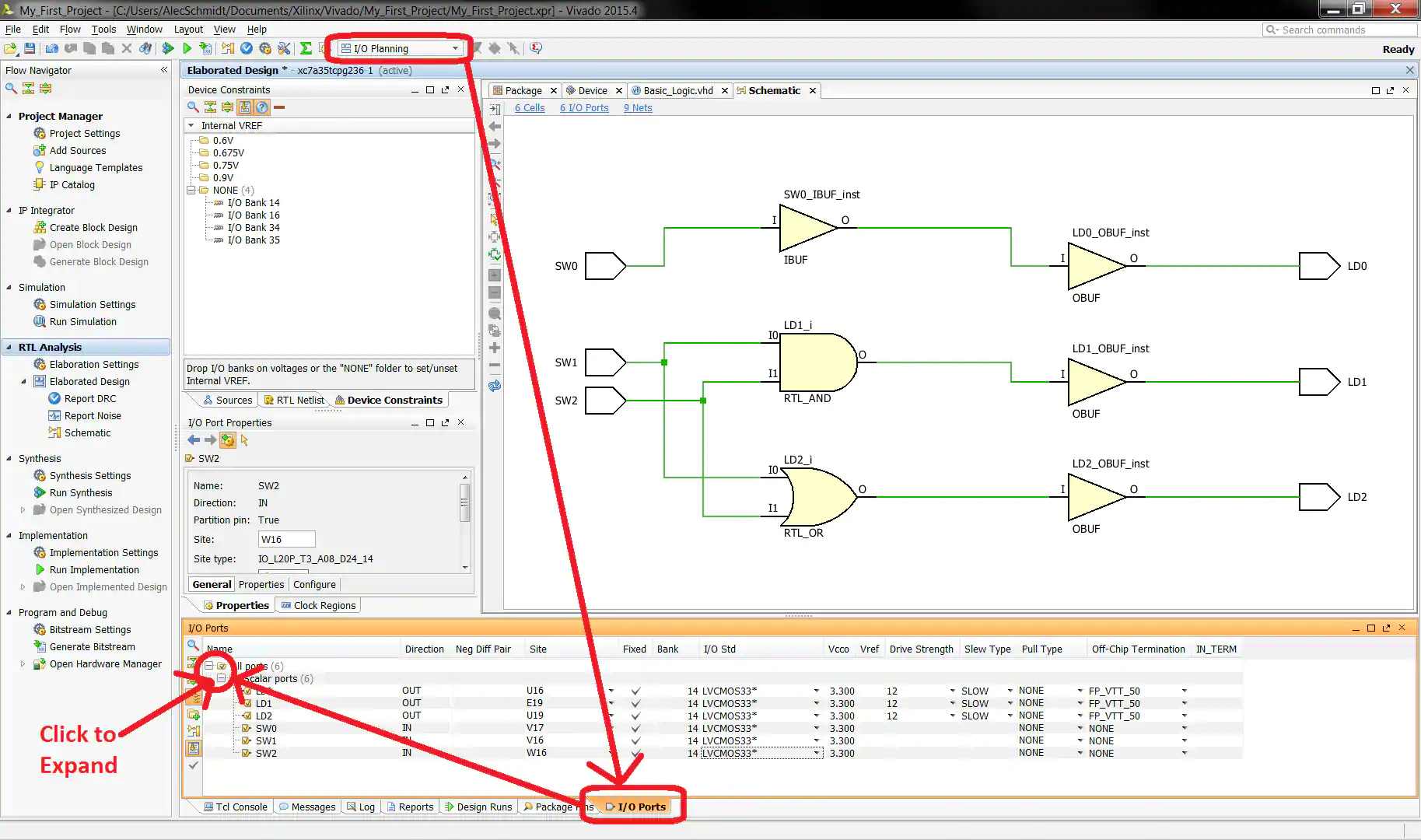
The port names and directions match the previously entered VHDL code. You have to type in or select from each drop-down a “Site” for each to give it a valid physical pin assignment of your programmable logic device. You similarly need to assign the appropriate “I/O Std” to match your board’s supplied I/O bank power rail for each selected pin.
For those following along with the Basys 3 board, the pin “Site” assignments shown for each port will match the silkscreen on your board for convenience, and all the “I/O Std” selections should be “LVCMOS33”.
Once everything is properly entered, select File → Save Constraints from the Vivado top drop-down menu.

Constraints File Creation
Make sure the options shown are selected in the “Save Constraints” popup, and for the sake of following along enter “Basic_Logic” for the “File name”. Click the “OK” button when finished.
You can normally enter anything you like for the “File name” as long as it’s valid, and it certainly isn’t required to match your HDL file name like this example, but always make certain there are NO SPACES!

The constraints file can be viewed and manually edited by double-clicking on it inside the “Sources” sub-tab of the “Sources” window. Open it for viewing, but for now leave it unedited.

Synthesis and Implementation
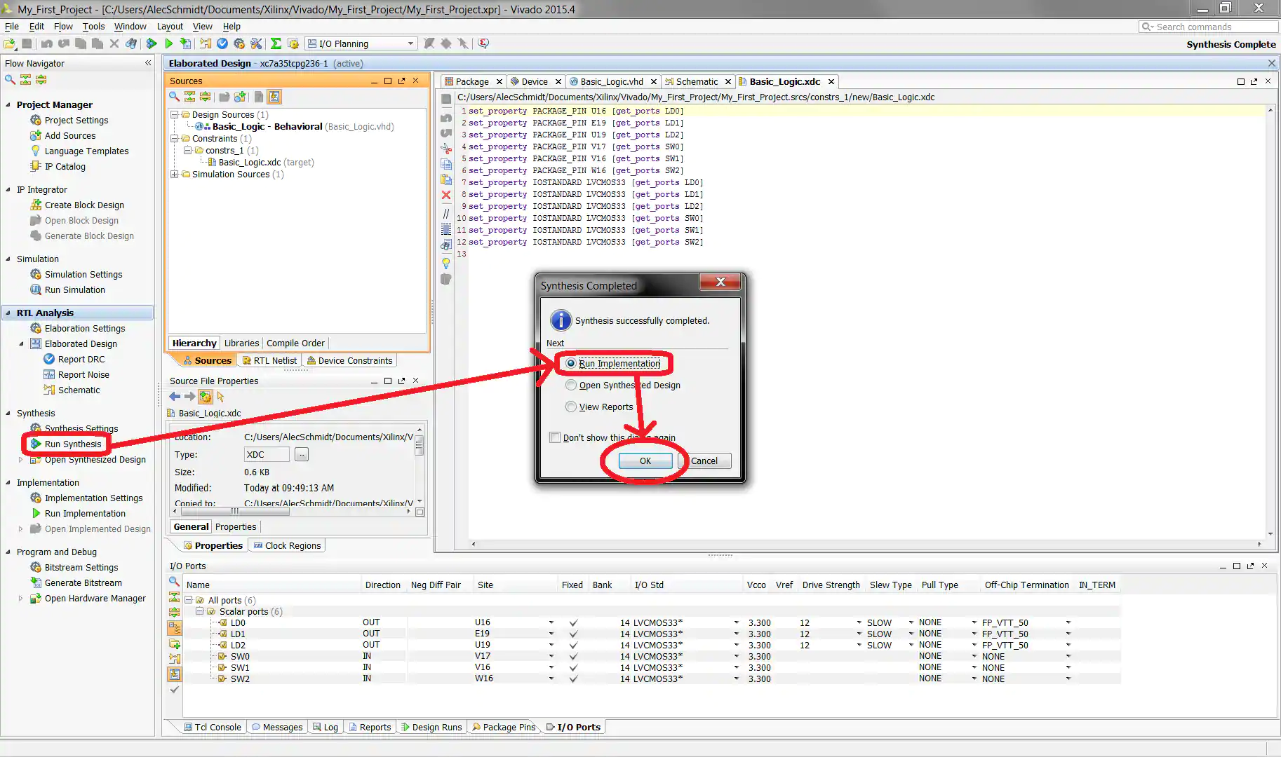
Now click on “Run Synthesis” under the Synthesis phase of the Flow Navigator. It will take some time for Vivado to finish. If you get the “Synthesis Completed” popup shown, select the “Run Implementation” radial and click the “OK” button. If not you can instead click “Run Implementation” under the Implementation phase of the Flow Navigator after synthesis completes. It will again take some time for Vivado to finish.
Program and Debug
Generate Bitstream
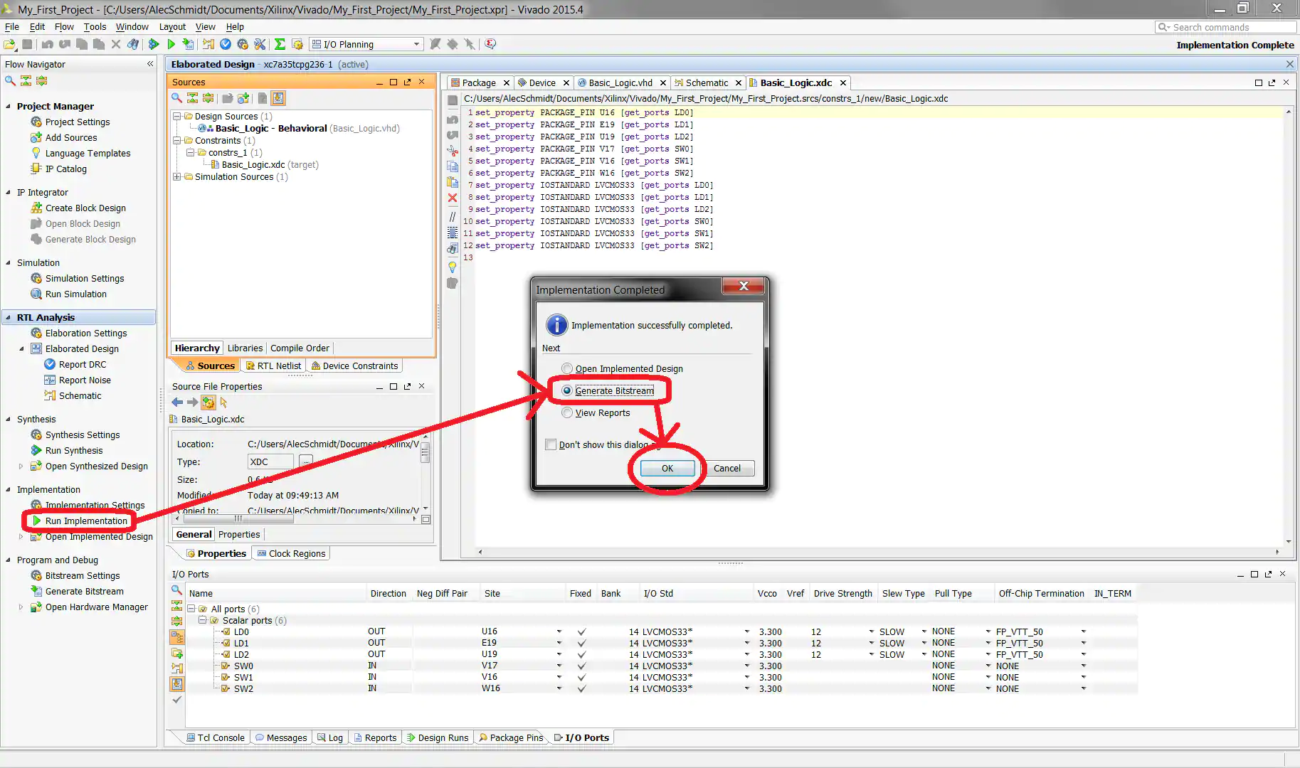
If you get the “Implementation Completed” popup shown, select the “Generate Bitstream” radial and click the “OK” button. If not you can instead click “Generate Bitstream” under the Program and Debug phase of the Flow Navigator after implementation completes.
If you get the “Bitstream Generation Completed” popup shown, select the “Open Hardware Manager” radial and click the “OK” button. If not you can instead click “Open Hardware Manager” under the Program and Debug phase of the Flow Navigator after bitstream generation completes.

Open Target
Now click “Open Target” under the Program and Debug phase of the Flow Navigator and then “Open New Target…” from the menu that appears. You will need to have already connected your JTAG programmer and/or development board to your computer, powered it on, and installed any necessary drivers to continue.

The Open New Hardware Target wizard will launch, click the “Next >” button to proceed.

Select “Local server (target is on local machine)” from the drop-down if it isn’t already, and then click the “Next >” button to proceed. Vivado will work for a moment to find any valid target devices connected to your local machine.

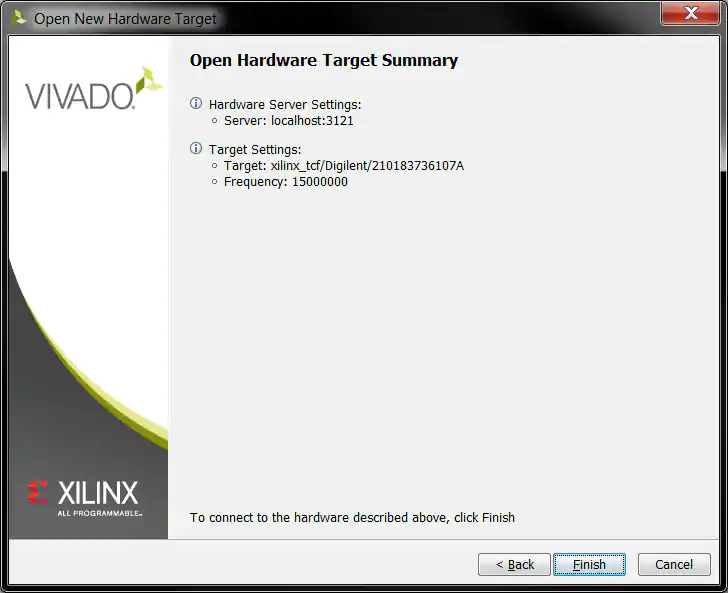
If all goes well you will see something like what’s shown here matching your specific hardware. Select your specific JTAG hardware target and programmable logic device and click the “Next >” button. Note that you have the option to change the “JTAG Clock Frequency”, but it’s reasonable to start with the default setting and only make adjustments later if necessary.

Click the “Finish” button and Vivado will attempt to connect to your specified hardware.
Program Device
Now click “Program Device” under the Program and Debug phase of the Flow Navigator and then your specific device from the menu that appears.

The “Program Device” popup that appears should have the file path to the bitstream file you generated automatically filled in. Select the “Enable end of startup check” check-box if it isn’t already and then click the “Program” button. Vivado will work for a moment, but if successful, when everything is finished your device should be programmed and ready for you to verify its proper behavior.

For those following along with the Basys 3, toggle switches SW0-SW2 and verify the previously described correct behavior of LEDs LD0-LD2.