This is a subsidiary page to the Fan Selection & Application Guide, which elaborates on the different values for the Bearing Type attribute used to characterize AC and DC fans at Digi-Key. The implications for fan longevity are discussed, and teardown photos of sample units with different indicated bearing types are presented.
Most air movers involve a union of rotating and non-rotating parts, and the bearings used to interface the two are typically a limiting factor for a given device’s durability, as well as being a major influence in how much acoustic noise a device makes in operation. Consequently, they’re of some interest in the selection and operation of a fan.

Figure 1. Bearing types among fans listed at Digi-Key
Ball Bearings
Ball bearings provide a low-friction interface between rotating and non-rotating parts through geometric means, placing hardened metal or ceramic spheres between two smooth surfaces called races , allowing for a rolling contact to occur. Because of part geometries and manufacturing tolerances, the contact area between the balls and the races is quite small, and the pressures that result from loads applied to the bearing are significant—it’s a situation not entirely unlike walking barefoot across a concrete floor littered with marbles. As a result, ball bearings are comparably limited in their load carrying capacity, and more vulnerable to damage from shock or impact than other bearing types. Though necessary in practice, lubrication is not a fundamental component of a ball bearing’s function, making them less susceptible to lubricant loss or degradation compared to sleeve bearings and their derivatives.
Wear and tear on a ball bearing comes in various forms, such as pitting of the contact surfaces or subtle changes in geometry such as rolling elements becoming non-round or dented. Shock loading, corrosion, foreign material contamination, or incorrect installation are all potential causes of such. As such imperfections increase in number and grow in severity, the mechanical fit of the assembly loosens and the various pieces become more free to rattle around, resulting in both an acceleration of the rate at which wear occurs and increased noise levels. A failing ball bearing will tend to provide advance notice audibly, which can be advantageous from a maintenance perspective.
Relative to sleeve bearings generally, ball bearings tend to be more costly, noisier initially and increasingly so with wear, more durable (particularly at higher operating temperatures) and generally insensitive to mounting orientation.

Figure 2. (L) A ball-bearing fan prepared for disassembly. Removing the label (R) reveals a finely-machined brass mounting and one of two ball bearings.
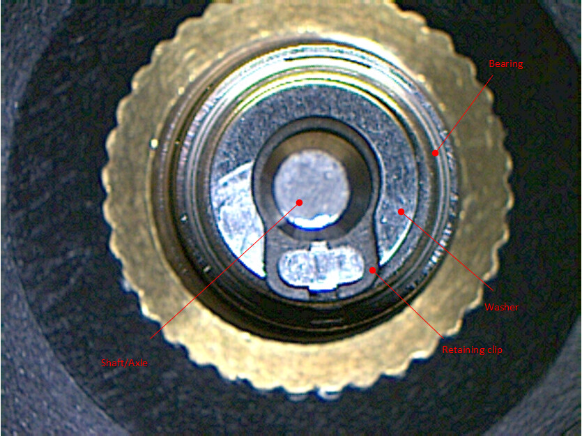
Figure 3. A closer look at the strut-side ball bearing, showing the retaining clip which fits into a groove on the fan’s shaft, holding the assembly together.

Figure 4. The disassembled fan with the various portions of the bearing system highlighted. No destructive disassembly was required to reach this stage; replacement of worn bearings would be possible.

Figure 5. A view of the motor structure, showing windings, winding former, and stator laminations.
Sleeve Bearings
Sleeve bearings of the sort found in small fans are much simpler than ball bearings, being essentially just a shaft in a tube. While this might seem to be a rather friction-y arrangement with two surfaces simply grinding away against each other, when properly executed the shaft is actually supported on a film of lubricant entrained between the two surfaces; in a sense, the shaft is “water skiing” within the tube. Importantly, a lubricant must be present for the system to function properly; just as water skiing on a dry lake bed doesn’t work so well, neither does an unlubricated sleeve bearing.
In small fans, the bearing sleeve is typically formed from a copper-based alloy using powder metallurgy processes to produce a solid, yet highly porous material capable of absorbing lubricant in a sponge-like manner. Variations in materials, process, and lubricant selection can give rise to differences in sleeve bearing performance, and may not be readily discernible by simple visual inspection.

Figure 6. An end-view drawing of a basic sleeve bearing. (Relative sizes and clearances are exaggerated)
Figure 7. A disused (for obvious reasons) sleeve bearing fan prior to teardown. (warning–loud audio…)
The geometry of sleeve bearings leads to a larger area of contact between surfaces, and consequently sleeve bearings tend to be more shock tolerant than ball bearings. The smaller number of moving parts relative to ball bearings and the fact of their being supported on a fluid lubricant film also leads to sleeve bearings being more quiet on balance relative to ball bearings, when things are working properly. The necessity of a lubricant being present however is a source of vulnerability; sleeve bearings don’t last long if the lubricant leaks, breaks down, or runs away from where it’s needed. Elevated operating temperatures accelerate lubricant breakdown and shorten service life more acutely for sleeve than ball bearings. Furthermore, sleeve bearing fans are preferably operated in a shaft-horizontal position only, to mitigate lubricant leakage. As can be seen from the following photos, operation with the hub pointing downward is likely to result in the lubricant promptly leaking into the hub for many sleeve bearing construction styles, resulting in prompt failure.
In summary, compared to ball bearings, sleeve bearings tend to be less costly, more quiet, shorter-lived, more tolerant to mechanical shock, and less flexible with regard to mounting position.

Figure 8. The acoustically offensive fan with sticker removed; no bearing access available from this side.

Figure 9. Removing the rotor assembly by melting the plastic at the axle attach point. Unlike the ball-bearing fan above, this example does not lend itself to non-destructive disassembly.

Figure 10. Sleeve removed, the white plastic retaining ring beneath it is now visible.
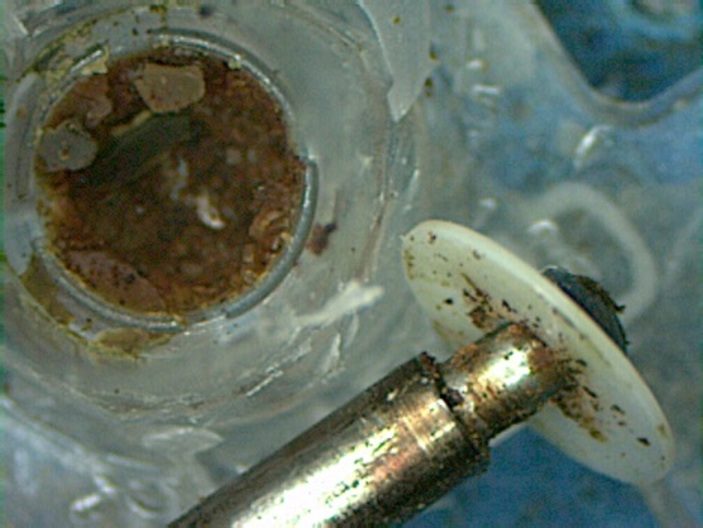
Figure 11. The axle with retaining ring re-applied to show attachment. After the sleeve had been pressed & staked into place on top of it and lubricant added, the rotor & axle assembly would have been pressed into place, and captured by the white plastic retaining ring. Note again the crumbly, paste-like character of the the lubricant’s remains, and the sticky residues thereof that cling to the shaft, retaining ring, etc. An adhesive effect caused by these residues is a likely cause of the excessive noise produced. Based on the accumulation of lubricant remains and their dessicated state, it seems likely that this fan was used in a shaft-vertical position, likely as a PC case fan.
Sleeve Bearings by Other Names
Ball bearings are the standard by which other small-fan bearing systems are judged. Various tweaks and augmentations to the basic sleeve bearing concept have been made in an effort to obtain ball bearing-like longevity at sleeve bearing cost and noise levels, with varying degrees of success. There is also an established resale trade in small DC fans, wherein products purchased from an OEM are sold under a private label. Since such products lack meaningful distinction from others purchased from the same source, creative writing is often used in an effort to create an appearance of differentiation.
The end result is that a ball bearing-equipped fan is likely to be advertised plainly as such with little further embellishment, while sleeve bearing fans (essentially all the rest) are often shrouded in a thick fog of marketing copy that makes it difficult to distinguish whether a given product actually sports some incremental improvement, or is simply a purchased industry-standard product. In the interest of providing a more objective comparison of these different sleeve bearing systems, representative examples were dismembered for display here.
Hydro-Wave

Figure 12.
Bearing: Hydro-Wave
Manufacturer: Panasonic/NMB
Part Number: FBL09A12H1A
Lifetime Rating: 50K hours @ 40°C, 65%RH (L10)
Operating Temperature Range: -10~+70°C
An older sleeve bearing variant from a division of Panasonic now owned by NMB and featured on a variety of obsolete products (notably the Panaflo brand) the example studied included several features not found on others.
Though rather difficult to find since the system has been discontinued, marketing literature from the time highlighted the thrust plate which was rotationally fixed to the fan shaft as a feature, indicating it’s effect as creating a fluid-bearing effect for axial shaft forces, e.g. the thrust force experienced by the hub & blade assembly in the opposite direction of air movement.
Though well-regarded during its heyday, the hydro-wave bearing system studied contained a relatively large number of small, high-precision components which likely resulted in comparably high manufacturing and assembly costs.
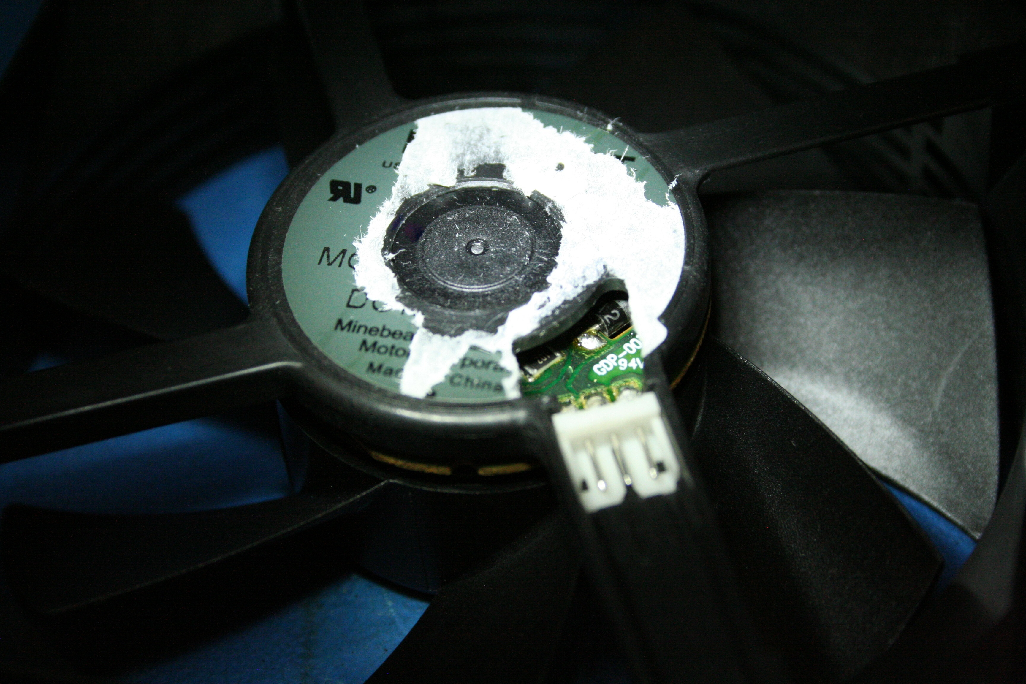
Figure 13. Beneath the sticker, a solid plastic molding is found, precluding lubricant leakage when fan is in a shaft-vertical/struts-down position. This example also featured a connectorized lead attachment.

Figure 14. Unlike most other examples studied, attachment of the fan blades to the shaft was achieved using a press-fit to a metal insert in the fan hub, beneath which is found a distinctive component made of white plastic.

Figure 15. Connector removed, the motor structure was found to be attached via a plastic-to-plastic press fit between the bearing housing and the strut molding.
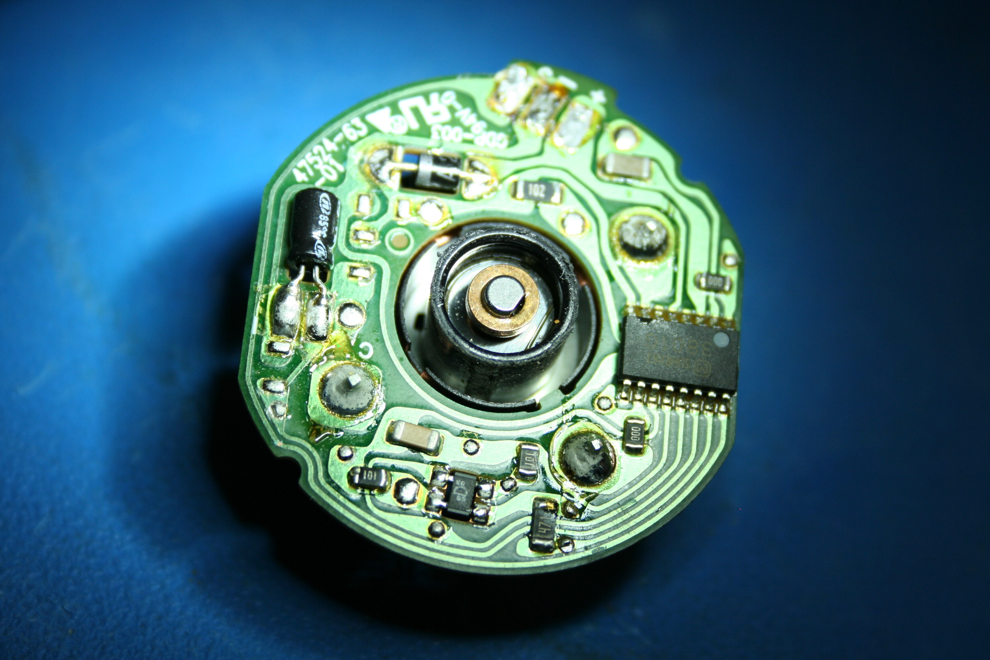
Figure 16. A closer view of the strut-side of the motor structure.
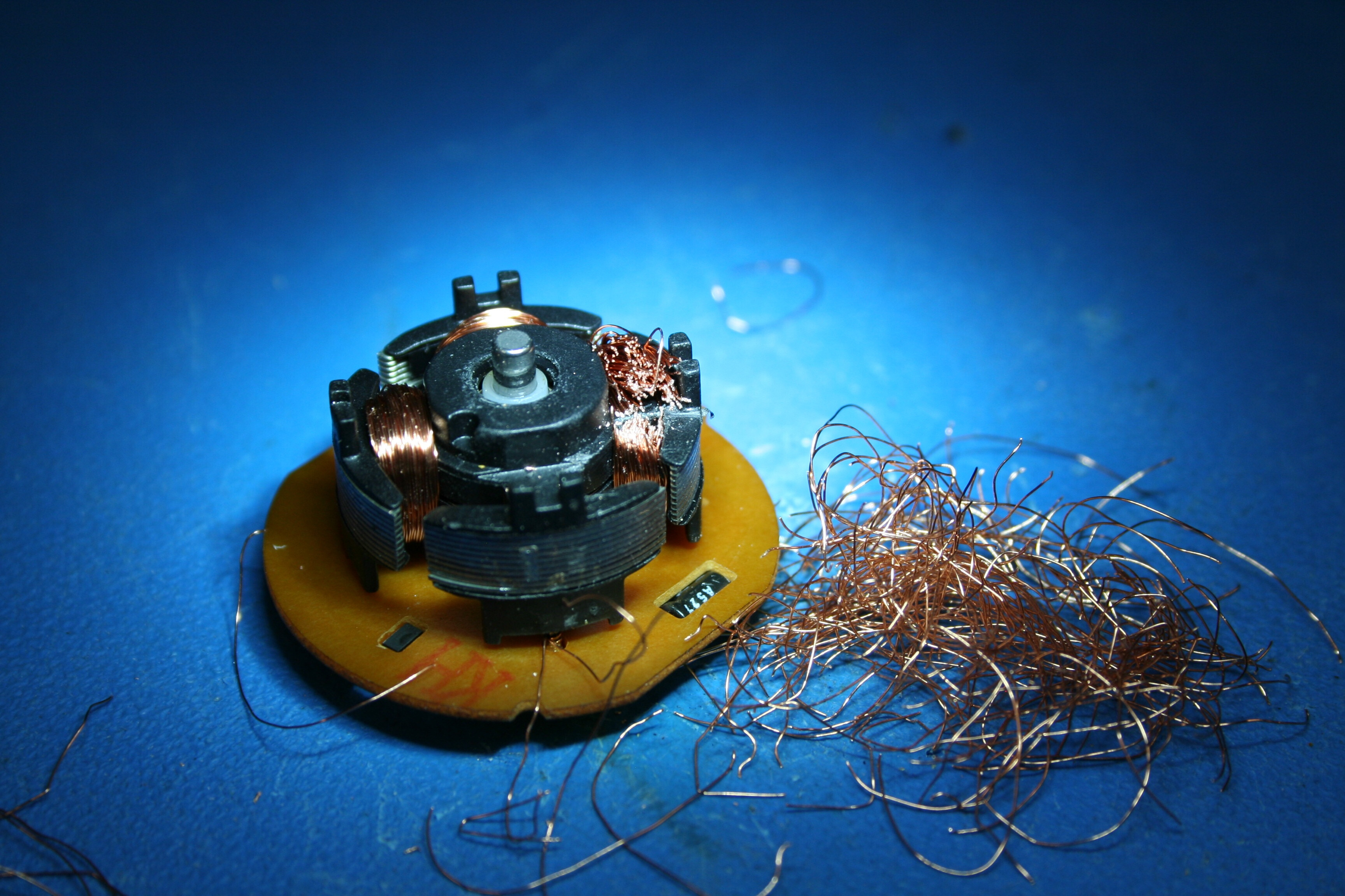
Figure 17. Windings being removed; initial appearances suggested they may have had a role in bearing retention, which proved incorrect.

Figure 18. Removal of windings complete.
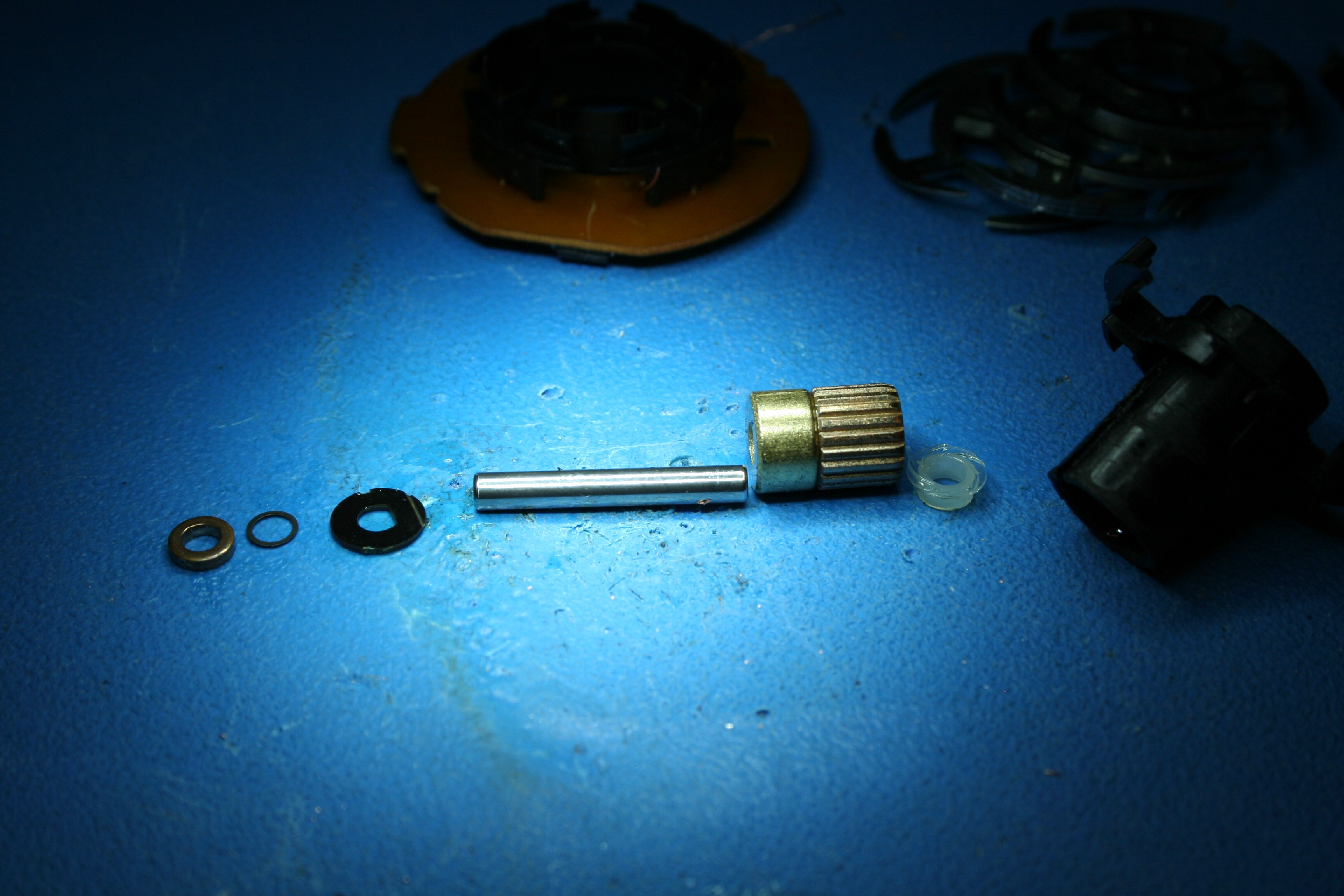
Figure 19. Above: components of bearing system laid out in order of assembly. Bearing retention was achieved by press-fitting the yellow-metal bushing into the plastic portion at the right of the image.

Figure 20. A closer view of the unique plastic component, which was found to be friction-fit to the shaft. Note the spiral raised regions; considering the direction of fan rotation, it would appear that their effect would be to force lubricant into the space between shaft and sleeve.

Figure 21. The bearing system re-assembled. The small red-metal ring was press-fit on the the shaft end providing retention, while the flatted shaft end provided positive engagement with the thrust plate having a small groove in its surface (visible in other photos).
Hydrodynamic

Figure 22.
Bearing: Hydrodynamic
Manufacturer: Qualtek
Part Number: FAD1-08025CHHW11-A
Lifetime Rating: 40K hours @ 40°C
Operating Temperature Range: -10~+70°C
This example of a sleeve bearing described as “hydrodynamic” was exceedingly similar to a later example of one described as having a “sealed sleeve” construction. Distinguishing these from others is the use of an o-ring seal and metal cup fastened in place hear the hub end of the shaft by a (presumably) thermal staking process, resulting in what would appear to provide a comparably robust seal against lubricant loss/leakage relative to some other systems.

Figure 23. Beneath the label is a fully sealed molding, precluding lubricant leakage through this path.

Figure 24. Hub & blade assembly removed, showing motor & magnet structure.

Figure 25. A closer view of the motor structure. Retention of the bearing sleeve appears to be achieved using a press fit augmented with some form of staking around the perimeter of what appears to be a metal insert.
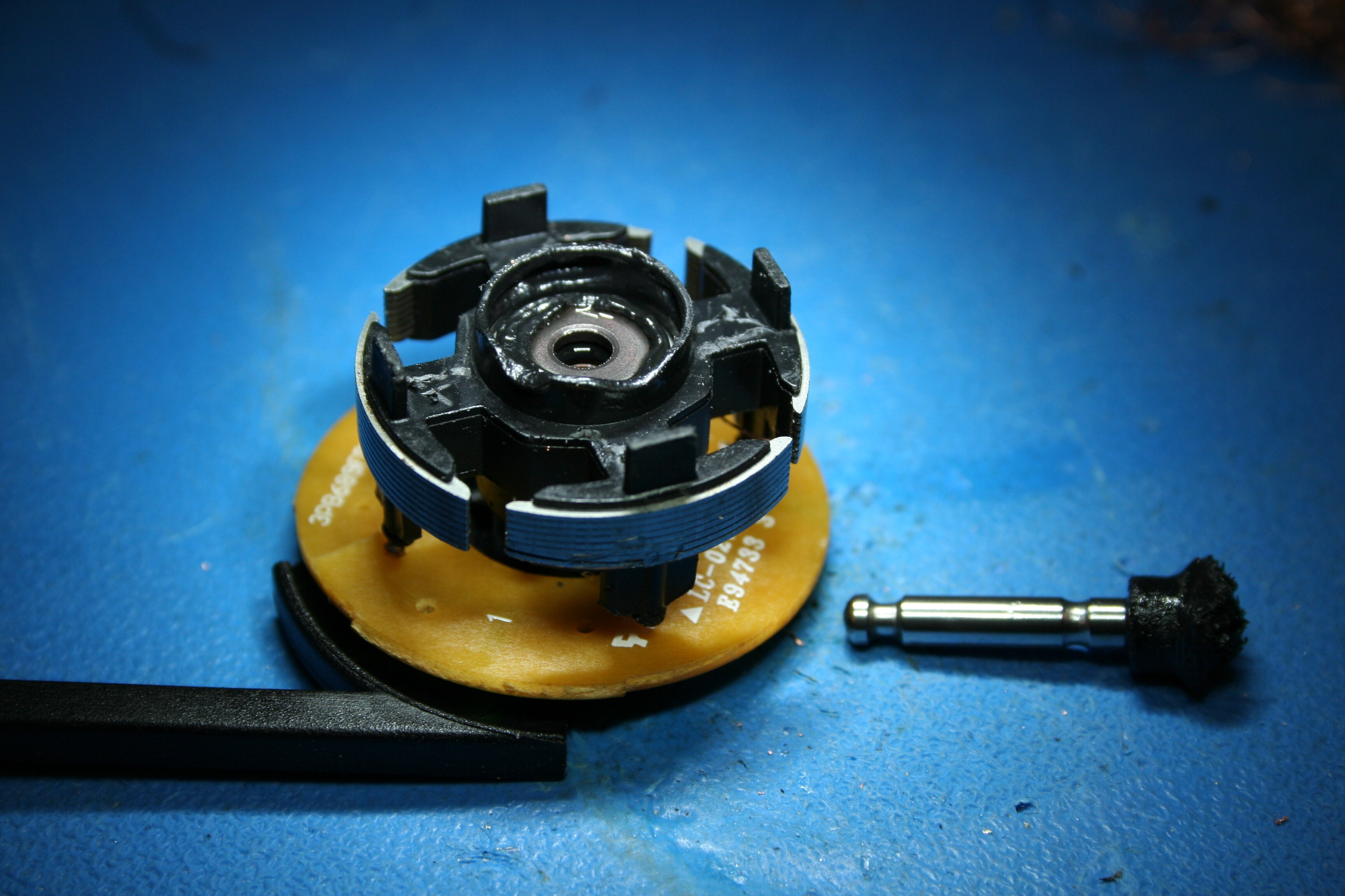
Figure 26. After removing shaft forcibly, an o-ring beneath the metal insert comes into view along with a corresponding groove in the shaft, apparently a seal against lubricant leakage.

Figure 27. Motor circuit board removed, a strut-side view of the remaing motor assembly.

Figure 28. Hub-side view of remaining motor structure with top plastic cut away.

**Figure 29.**stator laminations separated from plastic housing the bearing sleeve.

Figure 30. Metal cap insert removed, o-ring and upper surface of bearing sleeve is visible.

Figure 31. Bearing assembly re-assembled after being removed. Shaft retention is achieved via the small plastic disc engaging a groove near the end of the shaft, which is free to rotate independently of the shaft.
Omnicool

Figure 32.
Bearing: Omnicool
Manufacturer: CUI
Part Number: CFM-9225V-230-340
Lifetime Rating: 70K hours @ 40°C, 65% RH
Operating Temperature Range: -10~+70°C
The Omnicool bearing system is a sleeve bearing variant marketed by CUI, which bears an uncanny resemblance to the Vapo bearing system from Sunon. A distinction common to both is the inclusion of a circular ferrous metal plate at part of the motor stator assembly. The attraction between this plate and the rotor assembly is claimed to stabilize the rotor and reduce the occurrence of occasional contact between shaft and journal during operation, reducing wear.
Sealing of the hub-side shaft end against lubricant loss did not appear to be particularly robust, and the structure of such was found to be very similar to the standard sleeve bearing example from Sunon also studied. The clip-like component providing axial retention of the hub/rotor assembly was found to be similar/identical across the three.

Figure 33. Beneath the sticker, the strut-side molding is fully enclosed, preventing lubricant leakage from this end.

Figure 34. view from the hub side of the fan prior to removal. Note the multiple circular cuts into the periphery of the hub between blades, presumably an effort to balance the hub & blade assembly.

Figure 35. Hub & blades removed, the motor stator assembly comes into view. Note the ferrous metal ring structure near the bottom.
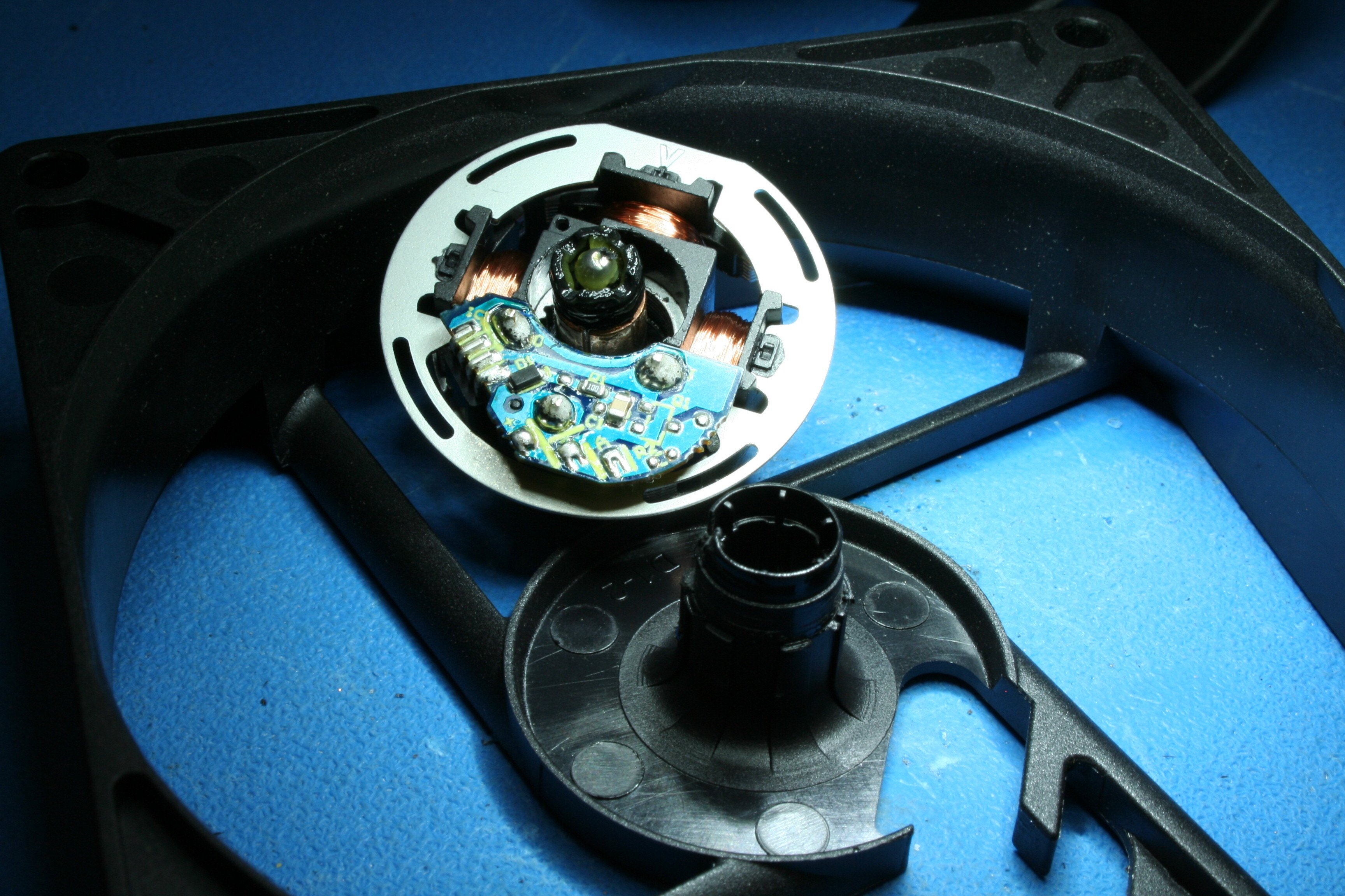
Figure 36. Strut-side molding separated from motor assembly. Fastening of the two appears to occur primarily via friction fit between stator laminations and the strut-side molding.

Figure 37. Shaft removed. Sealing of the hub side of the shaft against lubricant leakage appears to rely on the attraction of the rotor magnet to the circular metal structure holding the flat regions of plastic in place against each other.

Figure 38. The excised shaft & bearing assembly, reassembled next to the motor structure. Rather than a small white disk, a larger retention clip made of black plastic is used for shaft retention, though not rigidly fixed against rotation with the shaft.
Sealed Sleeve

Figure 39.
Bearing: Sealed Sleeve
Manufacturer: Orion
Part Number: OD8025-24HSS
Lifetime Rating: 50K hours (L10, Temp. not specified)
Operating Temperature Range: -10~+70°C
The sealed sleeve offering studied was found to be extremely similar in its inner construction to the hydrodynamic example studied earlier. While this similarity cannot be generalized to all devices marketed with similar bearing descriptions on the basis of this one example, it does illustrate how distinctions in marketing do not necessarily translate into readily discernible differences in the actual product.

Figure 40.

Figure 41.

Figure 42.

Figure 43.

Figure 44.
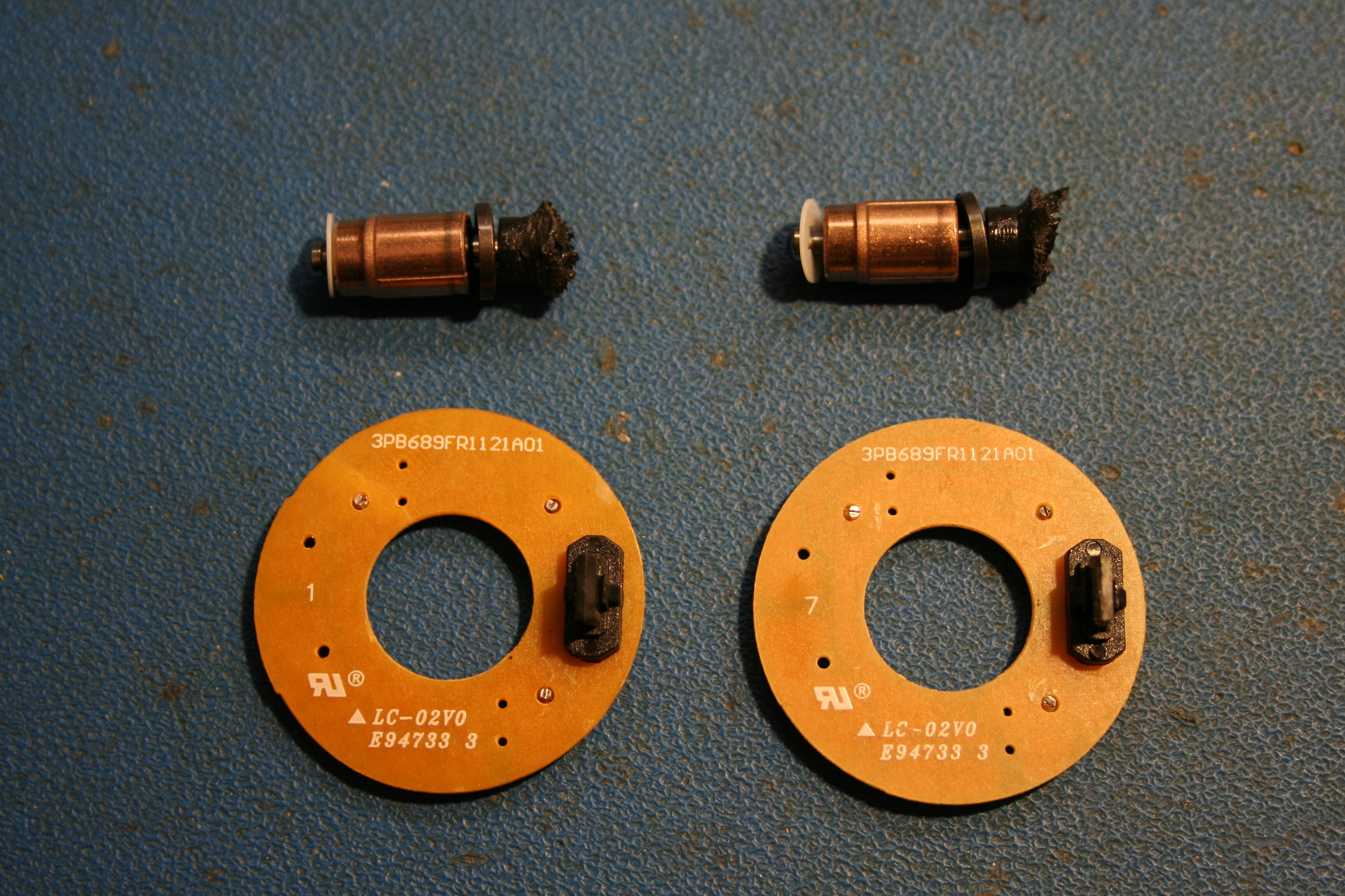
Figure 45. Comparison of motor circuit boards and bearing structure between the examples of hydrodynamic (left) and sealed sleeve (right) bearings studied.
Sintec
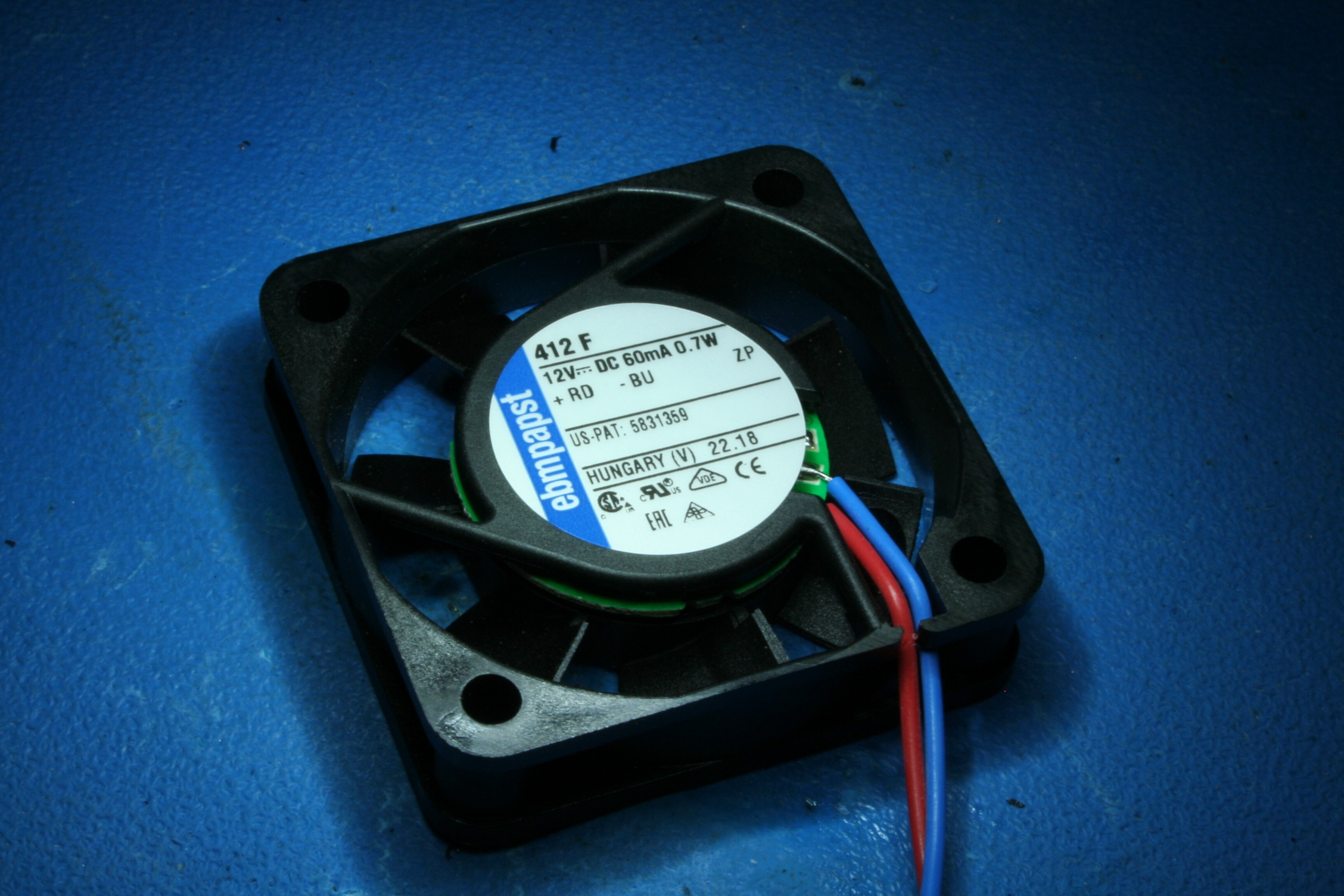
Figure 46.
Bearing: Sintec
Manufacturer: ebm-papst
Part Number: 412F
Lifetime Rating: 45K hours @ 20°C, 17.5K hours @ 60°C (L10)
Operating Temperature Range: -20~+70°C
The Sintec sleeve bearing designation is ebm-papst’s version of a standard sleeve bearing. The example studied here was a model significantly smaller than most of the others studied, for reasons of availability at the time of selection. The general construction of the bearing system is therefore different from the others and not directly comparable.
in a nutshell, Sintec bearings are well-executed sleeve bearings that like most others, feature a porous sleeve structure to facilitate lubricant flow. When fans having similar specifications are compared, those with Sintec bearings generally compare well with other sleeve bearing variants in terms of rated lifetime.

Figure 47. Beneath the label, the bearing structure is not fully sealed. instead, 3 holes are present in the molding to allow the motor structure to be staked into place.

Figure 48. A similar set of holes exits in the fan hub as found on the strut side. presumably, these exist to accomodate staking also.

Figure 49. The motor structure removed from the strut molding. The three impressions in the outer sleeve are the deformed regions from the staking process used to affix the motor structure to the frame. Shaft retention was provide by a small polymer clip fitting a groove in the shaft.

Figure 50. the reverse side of the motor structure, after separation from the hub/blade assembly.

Figure 51. Actual bearing sleeve removed from the motor structure, showing fit to the shaft.

Figure 52. The sintec bearing sleeve.
Sleeve

Figure 53.
Bearing: Sleeve
Manufacturer: Sunon
Part Number: EF80251S1-1000U-A99
Lifetime Rating: Not given
Operating Temperature Range:Not given
This example of a fan described as simply having a “sleeve” bearing shares some similarities with examples of both the Vapo and Omnicool bearing examples studied. The means of axial shaft retention appears common to the three, and the motor stator structure and hub-end sealing appear to be similar between the Omnicool and sleeve examples.
[wrap=“center”]

**Figure 54.**Beneath the label, a fully-sealed bearing enclosure.

Figure 55. Hub & blades removed, a familiar-looking motor structure is found.

Figure 56. bottom side of motor structure.
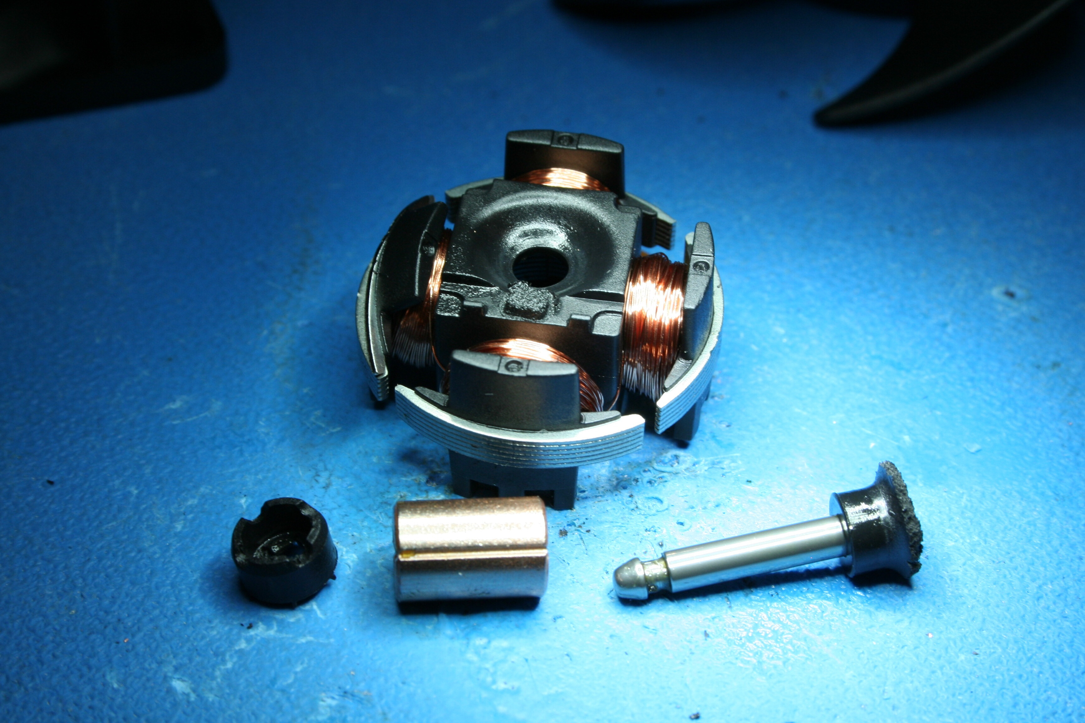
**Figure 57.**sleeve bearing structure disassembled.

Figure 58. (L-R): Sleeve bearing, Omnicool Bearing, and Vapo bearing motor structures (hub side).

Figure 59.(L-R): Sleeve bearing, Omnicool Bearing, and Vapo bearing motor structures (strut side).
Superflo

Figure 60.
Bearing: Superflo
Manufacturer: Delta
Part Number: AUB0812VH-AIT
Lifetime Rating: 50K hours @ 40°C, 65% RH
Operating Temperature Range: -10~+60°C
This example of a Superflo (Delta Electronics) sleeve bearing fan is most notably distinguished from the others by implementing the axial shaft retention mechanism near the hub end of the shaft, using a white cap-like piece which engages a groove in the shaft, being distorted slightly during assembly.
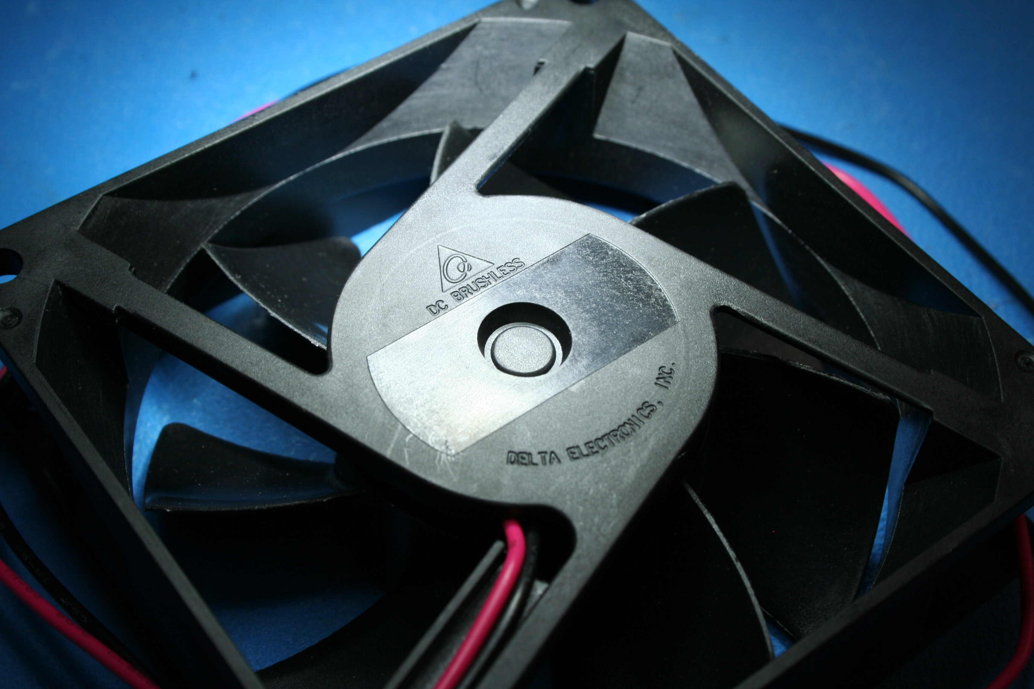
Figure 61. Bearings are enclosed fully on the strut side.

Figure 62. Hub-side view prior to disassembly.

Figure 63. Hub & blades removed.

Figure 64. Motor structure removed from strut/frame molding. Retention provided by press fit with stator laminations and snap-like engagement with white cap.

Figure 65. Cap removed from motor shaft.

Figure 66. Closer view of cap as installed on shaft. Note loose fit of cap in groove.

Figure 67. Shaft & cap reassembled to strut/frame molding absent hub or motor structure.

Figure 68. Fit of sleeve in frame/strut molding.

Figure 69. Isolated bearing assembly, including a small circular insert apparently functioning as a spacer or axial bushing of some form.
Vapo-Bearing
Figure 70.
Bearing: Vapo-Bearing
Manufacturer: Sunon
Part Number: EF80251S1-1000U-A99
Lifetime Rating: 70K hours @ 40°C, 65% RH (L10)
Operating Temperature Range: -10~+70°C
The example of Sunon’s vapo bearing system incorporated the ferrous ring also found on the Omnicool bearing, the axial retention system found also on the standard Sunon sleeve bearing example, and a different hub-side cap mechanism not found in the other examples. In the manufacturer’s marketing copy, the ferrous ring appears to be associated with the MagLev term, while that which distinguishes the company’s ‘sleeve’ from ‘vapo’ bearings is not immediately apparent from inspection.

Figure 71. The four square holes beneath the label avoid entry into the bearing space.

Figure 72. Prior to removal of hub & blade assembly.

Figure 73. Removal of hub & spokes reveals a somewhat familiar-looking motor structure, albeit with a distinctive hub-end cap assembly apparently retained with an array of latch fingers.

Figure 74. A closer view of the top-side motor structure.

Figure 75. Motor structure removed, revealing a familiar-looking circuit board, axial retention mechanism, and glop of lubricant.

Figure 76. Excised bearing system with top view of motor structure.
1 Ball 1 Sleeve
Figure 77.
Bearing: Superflo (1 Ball, 1 Sleeve)
Manufacturer: Delta
Part Number: AUB0812VH-AIT
Lifetime Rating: 50K hours @ 40°C, 65% RH
Operating Temperature Range: -10~+60°C
Lastly, we consider an example of a ball + sleeve bearing system. It’s not especially populous among Digi-Key’s offerings, with most listed products not obsolete being found in the sub-40mm size class.

Figure 78. Label removed, the sleeve bushing is visible. The shaft is held in place axially with a small polymer clip, with a thin red polymer-film washer placed between the two.

Figure 79. The sleeve bushing removed from it’s plastic housing. Presumably, the bevel found on the inner edge would act as a reservoir for lubricant.

Figure 80. The hub and and rotor assembly motor assembly removed, showing the ball bearing supporting the hub side of the shaft.