This educational post presents the teardown of an older phased out SICK WL27-3P3402S17 RAY26 reflex array sensor. The pictures show the sensor’s basic components with an emphasis on the lens used to produce a collimated light beam. Let’s begin with Figure 1, showing the sensor assembly removed from the protective case.
This article is part of the DigiKey Field Guide for Industrial Automation
Location: Understand It → Teardowns
Difficulty: ![]() Student — difficulty levels explained
Student — difficulty levels explained
Author: Aaron Dahlen | MSEE | Senior Applications Engineer, DigiKey
Last update: 06 Mar 2026
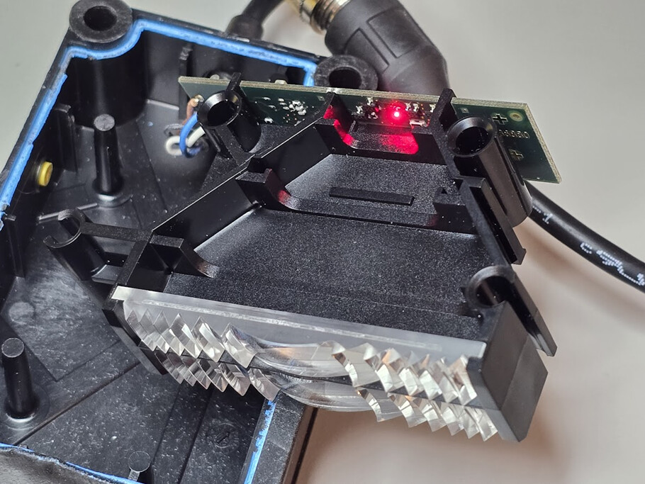
Figure 1: Image of a SICK reflex array sensor removed from its protective case.
Can the SICK sensor be repaired?
End-user repair is not recommended for several reasons:
-
Damage to the case. The adhesive holding the blue cover to the black case of the unit is very strong. Opening the case is like tearing the unit apart. The blue adhesive remnants are clearly seen in Figure 1. A damaged case will compromise the sensor’s IP67 rating resulting in shortened sensor life.
-
Components such as the PIC16F886 must be programmed. The microcontroller is almost certainly code-locked and few OEMs share the proprietary firmware.
-
The surface mount components aren’t excessively small, yet they require skill to replace without damaging the PCB.
-
As a common industry practice, few OEMs provide schematics. This is especially problematic with SMD components as the part numbers are often cryptic.
This is a classic miniaturization problem. Smart, small, and sealed are not repairable.
Tech Tip: Before you toss your SICK sensor, see if it is can be repaired by SICK or other authorized repair centers.
What is a reflex array sensor?
The SICK reflex array sensor uses a rectangular beam of light as shown in Figure 2. This beam is like a light curtain as opposed to the narrow beam of a conventional retroreflective sensor.
In Figure 2 we see that the light from the single visible red LED is focused into a collimated rectangular beam. It does this using a Fresnel-like lens (Figure 3), reminiscent of the maritime lighthouse lenses. This beam is then reflected by a “bicycle reflector” before returning to the light sensor via another lens. The amount of returning light is compared to a threshold to determine if an object is present.

Figure 2: The light from a single red LED is spread into a collimated beam.

Figure 3: Close-up of one of the sensor’s lenses.
Sensor Intelligence
Figure 4 shows the visible red LED along with the light sensor. Referring to Figure 1 we see how the LED light is formed into a rectangular beam. After reflecting, the light passes through another lens which focuses the returning light on the sensor.
Figure 4 also shows the PIC16F886 microcontroller. We can safely assume the microcontroller is used to establish the threshold sensitivity level for the received light beam. Refer to Figure 1, where we can just make out the yellow teach-in pushbutton plunger.

Figure 4: Image of the sensor’s PCB with visible red LED and return sensor surrounded by a black semicircle.
 Continue Exploring Industrial Control Systems
If this discussion was helpful, you may also want to explore:
 DigiKey Navigation
- Full Catalog: Industrial Control & Automation
 Related Foundational Articles
- OSSD Safety Signals: What the Waveform Tells a Safety Relay
- Light Curtain Teardown; Inside the Banner EZ-Screen LP
- Electronic Circuit Breaker Protector for Industrial Control
About This Author
Aaron Dahlen, LCDR USCG (Ret.), is a Senior Applications Engineer at DigiKey in Thief River Falls. His background in electronics and industrial automation was shaped by a 27-year military career as both technician and engineer, followed by over a decade of teaching.
Dahlen holds an MSEE from Minnesota State University, Mankato. He has taught in an ABET-accredited electrical engineering program, served as coordinator of an electronic engineering technology program, and instructed military technicians in component-level repair.
Today, he has returned to his home in northern Minnesota, completing a decades-long journey that began with a search for capacitors. Read his story here.